Attiny13 Software Uart Bascom
Bascom and AVR, Using small AVR's Bascom and AVR, Using small AVR's It does not get much smaller. Take a 'tiny' ATTiny13 SMD eight-pin chip.
See More: how to get es-388 v2.0 bluetooth usb driver. [Solved] how to install belkin bluetooth on 64 bit desktop. I hv downloaded the bluetooth usb adapter driver es-388, but after installation, bluetooth is still not working. And system property is still showing one item with yellow? 'This device is not configured correctly. Bluetooth usb adapter es 388 driver. Bluetooth Usb Adapter Es 388 Ar now has a special edition for these Windows versions: Windows 7, Windows 7 64 bit, Windows 7 32 bit, Windows 10, Windows 10 64 bit,, Windows 10 32 bit, Windows 8, Windows 7 Home Premium 64bit, Windows XP Home Edition, for home desktops and laptops 64bit, Windows 10 Home 64bit, Windows Vista Home Basic 32bit, Windows 10 Enterprise LTSB 64bit, Windows RT 64bit. Free Download ES-388 Bluetooth Dongle Drivers for Windows Vista, Windows XP, Windows 2000 http://zipwaves.blogspot.com/2009/03/.
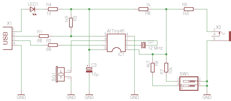
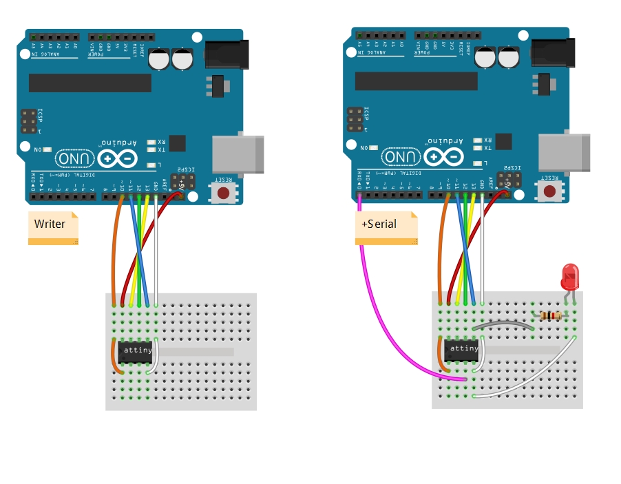
It has 1k program memory, 64 bytes SRAM, 64 bytes EEPROM. You can use five I/O pins in Bascom. It is tiny, but can run as fast as 20MHz! And it can still be programmed as any other AVR with only the SCK, MISO, MOSI and RESET pins. (I have used an SMD Led and current-limiting resistor soldered directly to the chip) Make sure you read the. Try this schematic: Start TWinAvr, and click on Config. These are the fuse settings of a blank ATTiny13: The ATTiny13 starts default with an internal RC oscillator at 9.6 MHz.

This is prescaled by 8, giving a clock speed of app. You can unprogram the CKDIV8 fuse, setting the clock speed to the full 9.6MHz. The ATTiny13 can run as fast as 20MHz, but then you need to set the CKSEL fuses to '00' and an external clock connected to Pin 2 (PB2/CLKI) Try this program to get a flashing Led: 'The ATTiny2313 is used. $regfile = 'ATtiny13.dat' $crystal = 1200000 Config Portb = Output Do Portb = 255 Waitms 50 Portb = 0 Waitms 50 Loop End But the ATTiny can do more.
It has a 10-bit ADC on pins 1, 2, 3 and 7. An example program to read one ADC channel: 'The ATTiny13 is used. $regfile = 'ATtiny13.dat' $crystal = 1200000 Config Portb.2 = Output Led Alias Portb.2 Config Adc = Single, Prescaler = Auto, Reference = Internal Dim Adcin As Word Open 'comb.1:9600,8,n,1' For Output As #1 Open 'comb.0:9600,8,n,1' For Input As #2 Start Adc Do Set Led Waitms 500 'get adc reading on channel 3 (pin 2 on attiny13) Adcin = Getadc(3) Print #1, 'adc ch#3: '; Adcin Reset Led Waitms 500 Loop End A software UART is used to send the ADC readings to the PC.
You may use Bascom's terminal program to display the results (Tools/Terminal emulator; then in the terminal emulator, do Terminal/Settings and set port to Com1 and speed to 9600 baud) Although in the program comb.0 is opened as input, it is not used in the program, but you could try sending commands to the ATTiny13. This program takes up slightly more than 50% of the ATTiny13 flash memory.
So, for 'tiny' tasks it fits the bill nicely!
Well we know 'baby sitting' on servo is wasting time. Updating every ms, so is good to have separated board and microcontroller to controlling the servo.
Unfortunately, servo controller out there is just over kill, and pricey. So this is where the idea come from. Using ATTiny13 or ATTiny 13A (anything that at least has min 1KB flash and 64 Bytes Internal SRAM will works ) This design using single layer PCB (bottom layer only) and the firmware only has 0,1 ms resolution. As i build this for proof of concept only, when i have time, i'll update the firmware and the PCB with double layer so i can put led for power indicator and RX indicator. The reason why i only using 0,1 ms is because the reliability for UART.
Program UART on ATtiny13. I showed an example of software UART for ATtiny13 and thus used the Arduino IDE as a development environment. ATtiny13 is clocked from the internal RC circuit.
The UART is very poor, its about 70% hit rate. So for using this, make sure you send the command at least 3 times. Its because this board only using internal clock, and bitbanging UART, since ATTiny13 does not has hardware USART/UART. The UART technique is developed by Eric Evenchick.
And if you take a look of his you even can use Half-duplex software UART single pin operation for this module. The command for this module only using UART. You can connect the RX pin to your arduino or other microcontroller TX pin.
It has 2 type of command. The first one is single update servo command, and the second one is for updating all servo on the same time.
If you playing with by Benjamin Gray you would using the second command for updating all the servo for pointing your MeArm to the point that you want instead of only one by one. Because the firmware is beta version, you have to trial n error to add some delay for each character, so the communication miss rate is decreased (especially for 2nd command for updating all the servos). This is the sample command communication for updating the servo: 1st type (single update servo command): sent_string( 'A10'); //sent servo A valuesent_string( '!' ); //sent command to move the servo _delay_ms( 200); //wait for servo movement using delay for reliable communication sample: sent_string( 'A');_delay_ms( 1); //give a breath for the bit bang UARTsent_string( '1');_delay_ms( 1); //give a breath for the bit bang UARTsent_string( '0');_delay_ms( 1); //give a breath for the bit bang UARTsent_string( '!' ); //sent command to move the servo_delay_ms( 200); //wait for servo movement another sample: //sent value for all servos and move the servos sent_string( 'A10B15C10D20!' ); /*from command above, if any miss communication of one or more servos value, the another value that received will be processed*/ 2nd type (updating all the servo) sent_string( 'A10B15C10D20*') //sent value for 5 servos and move the servos /*with asterisk '*' (star) command, if any missed value all servos will not executed*/ nb: • Because of hit rate UART less than 70% there is good for you to repeat the command 3-5 times.
